People occasionally ask me how I reverse-engineered my scanner. So I decided to write it all down here rather than answer the question repeatedly.
I have a Canon FB330P scanner. It's really nice, and was very fairly priced. The quality is great. I'm really happy with it.
What I'm no so happy with is Canon's driver. It's a Windows driver, naturally. And there's no support for linux (naturally). But the thing that really got me is that it doesn't actually work on my computer. As soon as I run it, it hangs the machine. I don't have any port conflicts or IRQ sharing or any of that crap. But I know that the Windows driver accesses the port directly, rather than going through the Windows API. And there's no way to tell it which port your scanner's on (it has to auto-detect it each time) so I deduce that it's feeling free to access ports it shouldn't touch and thereby crashing Windows. Now that is pretty shonky.
So, I decided that I'd try to reverse-engineer it and see how far I got.
Port-snooping programs for Windows were no use because the driver accesses the port directly. Getting Wine to do port-snooping sounded like more trouble than it's worth (I think it's become better since then though). I decided I had to (or perhaps I just wanted to) watch the IO lines on the parallel port change between the scanner and the PC and see what they did.
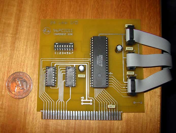
First of all... you need more than just another parallel port. You need 17 input lines to watch what's happening on the port's 8 data lines, 4 control lines and 5 status lines. I whacked up a 24-line parallel IO card from a kit when I decided to reverse-engineer my scanner. It's quite similar to this schematic. Basically it's an 8255 IO chip with two 74LS138s and a dipswitch attached to decode the address from the PC bus. The actual kit that I used can be purchased (AU$45) from Jaycar Electronics catalogue number KA1789
This kit gives you 3 8-bit ports of input. Very handy. I connected a 74LS241 buffer to each port (on a floating veroboard) to buffer the IO port and stop the computer exploding. In retrospect, it was a dumb chip to use because I had to do crazy wiring (I'm not experienced with electronics) You can see the entire setup below. Click on the images for a bigger version:

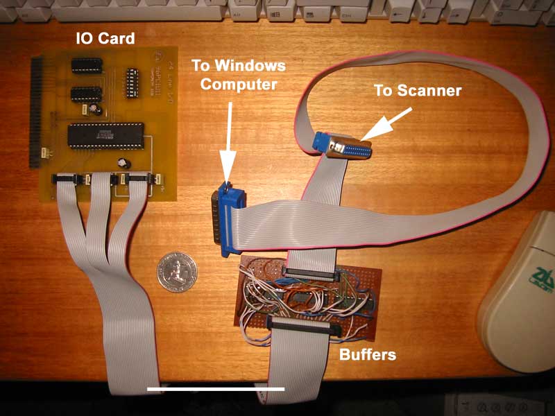
The 8255 IO card isn't meant for this type of work so there are a few workarounds involved. Firstly its speed is dependent on the speed of the computer it's in, so to get around that I used the fastest computer I had spare (a pentium 90) to do the data capture. I used the slowest computer I could find (a pentium 75 which I crippled by making everything slow in the BIOS) to do the Windows part. The other issue is that all lines aren't read at once, so there's a stepping effect from port to port. It's easy to account for that when reading the trace diagrams, though.
I wrote a few programs to drive the IO card in Linux. One to record the protocol and then save it, and another to print diagrams. Here's an example of the output:
          D7 D6 D5 D4 D3 D2 D1 D0 | C3 C2 C1 C0 | S7 S6 S5 S4 S3
   253528             || ||    ||      || || ||   || || || || ||
   253529                           || ||    ||   || || || || ||
   258820                              || || ||   || || || || ||
   260469                           || ||    ||   || || || || ||
   265818                              || || ||   || || || || ||
   302073       || ||       || ||      || || ||   || || || || ||
   302075       || ||       || ||      ||    ||   || || || || ||
   302076       || ||       || ||      || || ||   || || || || ||
   302078 || ||       || ||            || || ||   || || || || ||
   302080 || ||       || ||            ||    ||   || || || || ||
   302081 || ||       || ||            || || ||   || || || || ||
   302083       || ||       || ||      || || ||   || || || || ||
   302085       || ||       || ||      ||    ||   || || || || ||
   302086       || ||       || ||      || || ||   || || || || ||
   302088 || ||       || ||            || || ||   || || || || ||
   302090 || ||       || ||            ||    ||   || || || || ||
   302091 || ||       || ||            || || ||   || || || || ||
   302094 || ||       || ||            || || ||   || ||
   302095 || ||       || ||            || || ||            || ||
For more examples see the FB620P wakeup pattern with and without a scanner attached.
So basically that's how I did it...